
You are using an out of date browser. It may not display this or other websites correctly.
You should upgrade or use an alternative browser.
You should upgrade or use an alternative browser.
USB connection problem on go720
- Thread starter val
- Start date
dhn
Moderator
Welcome to TTF.
No video on dealing with the usb connector as such, but perhaps the info in this link for replacing the battery on that model may give you some insight.
See here:
https://www.tomtomforums.com/tomtom...730-920-930-battery-replacement-tutorial.html
No video on dealing with the usb connector as such, but perhaps the info in this link for replacing the battery on that model may give you some insight.
See here:
https://www.tomtomforums.com/tomtom...730-920-930-battery-replacement-tutorial.html
canderson
Moderator
- Joined
- Dec 28, 2007
- Messages
- 13,038
- Location
- Colorado, USA
- TomTom Model(s)
- GO720, GO740, GO 1535, Via 1535, Via 1605, GO 52, GO 600, GO 620, GO 630, GO Discover, TomTom Bridge
Are you certain it's the USB connection? Could very well be, but are you saying you don't see the green power light when connected? If it's just a lack of recognition of your unit when you plug it in, that COULD be a different problem. I had a 720 that required that I press the reset pin (bottom side, hole) every time I wanted to connect - for about 5 months. Then it miraculously "healed" itself and hasn't pestered me that way again since.My usb CONNECTION ON UNIT BECAME LOOSE.CANNOT CONNECT.is here a video on how to access it.I took off the cover but the USB is under and i dont want to damage the unit.
Val
I also had a problem with the actual connection, but it turned out to be the pins on my car charger connector, not the 720. What happens when you plug your 720 into the PC docking station?
canderson
Moderator
- Joined
- Dec 28, 2007
- Messages
- 13,038
- Location
- Colorado, USA
- TomTom Model(s)
- GO720, GO740, GO 1535, Via 1535, Via 1605, GO 52, GO 600, GO 620, GO 630, GO Discover, TomTom Bridge
OK - got it. Last chance before the hard part. I had the charger end of one of my cables start to get goofy. Finally had to scrap the cable. My nearly-new one gave me no problems. Do you have a spare USB A - USB miniB cable around (camera or whatever)? If so, give that a try. Also give it a try in the docking station. If that doesn't work, you've got (at a minimum) a desoldering and replacement job on your hands.The connector is very loose on the unit.The green light comes on briefely when i jiggle the wire.
Thanks,
Val.
USB conn.problem
Thanks for all your help.I had a trip out of town and ennd up buying a new GO 630 at Wallmart 99.00 cdn.But i woul still like to fix the old 720,chalenge,I succeded with the video help to take it apart and the USB connector was loose and just fell out.Problem is i dont know what was holding it in place originally.Where do you apply the solder*?Any help would be appreciated.
Val.
OK - got it. Last chance before the hard part. I had the charger end of one of my cables start to get goofy. Finally had to scrap the cable. My nearly-new one gave me no problems. Do you have a spare USB A - USB miniB cable around (camera or whatever)? If so, give that a try. Also give it a try in the docking station. If that doesn't work, you've got (at a minimum) a desoldering and replacement job on your hands.
Thanks for all your help.I had a trip out of town and ennd up buying a new GO 630 at Wallmart 99.00 cdn.But i woul still like to fix the old 720,chalenge,I succeded with the video help to take it apart and the USB connector was loose and just fell out.Problem is i dont know what was holding it in place originally.Where do you apply the solder*?Any help would be appreciated.
Val.
canderson
Moderator
- Joined
- Dec 28, 2007
- Messages
- 13,038
- Location
- Colorado, USA
- TomTom Model(s)
- GO720, GO740, GO 1535, Via 1535, Via 1605, GO 52, GO 600, GO 620, GO 630, GO Discover, TomTom Bridge
Ugh. NOT good. Chances are about 99.999% that the pads (the copper bits to which the components are soldered) and possibly even the traces (the copper bits that carry the signals around) have been torn right off the board. Repair would require fixing the connector to the board with adhesive and re-creating the connections between the connector and alternate points on the board (where the ripped up traces were connected electrically) with 30ga wirewrap wire or similar. It's NOT an easy job, by any means, especially at SMT sizes.I succeded with the video help to take it apart and the USB connector was loose and just fell out.Problem is i dont know what was holding it in place originally.Where do you apply the solder*?Any help would be appreciated.
Val.
Folks - I have been chasing details for past few days and looked at battery replacement tutorials, pcb fixes etc, and within this forum
on my 720 - my usb was ripped off the board (previous repair)
I am looking for a close up of this usb connection to determine the 5 pin traces back to points on the PCB
My unit has been repaired before but now having cleaned away all the extra solder/slag etc, I have discovered that the pads are missing for me to solder too.
I assume this board only has top and bottom layer - no traces within???
A schematic would be great
Any help would be appreciated
I am determined it will not get the better of me
cheers
O
dhn
Moderator
SuperMod canderson will likely see your post when he logs in here (a few hours from now). So check back since he is an expert in this area, as you may have noticed.........
Bump - still playing about with this unit.
I have managed to remove all the green film to expose the tracks under the connector to determine likely contact points, but as the usb connector was damaged - I would appreciate a close up of this area if anyone can assist
cheers
I have managed to remove all the green film to expose the tracks under the connector to determine likely contact points, but as the usb connector was damaged - I would appreciate a close up of this area if anyone can assist
cheers
- Joined
- Feb 10, 2011
- Messages
- 4,683
- Location
- London, UK.
- TomTom Model(s)
- Go520,720,XL Live, Start60,Go940,950,1000,1005,New500,New5000
Trouble is... won't any picture of a working device have the socket obscuring the view?
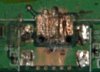
I have attached a pic - but this is best resolution I can get - note I have been able to clean away all the previous mess left by previous repair - so I am wanting to know the pad and traces - incase I have cut one
I have from left to right assumed
Pin 1 - V+
Pin 2 - D+
Pin 3 - D-
Pin 4 - Soldered but not sure if connected to pin 5
Pin 5 - Ground
I have from left to right assumed
Pin 1 - V+
Pin 2 - D+
Pin 3 - D-
Pin 4 - Soldered but not sure if connected to pin 5
Pin 5 - Ground
Attachments
Last edited:
- Joined
- Feb 10, 2011
- Messages
- 4,683
- Location
- London, UK.
- TomTom Model(s)
- Go520,720,XL Live, Start60,Go940,950,1000,1005,New500,New5000
- Joined
- Feb 10, 2011
- Messages
- 4,683
- Location
- London, UK.
- TomTom Model(s)
- Go520,720,XL Live, Start60,Go940,950,1000,1005,New500,New5000
Strange, it works for me. But its a "xxxxx.ru" URL, which is Russian I guess. That might be blocked for you for some reason?
Wikipaedia DOES number the pins 1-5, but the functions are listed similarly.
Wikipaedia DOES number the pins 1-5, but the functions are listed similarly.
dhn
Moderator
Could be the reason for the blockage. I'm at work and there are filters in place.
- Joined
- Feb 10, 2011
- Messages
- 4,683
- Location
- London, UK.
- TomTom Model(s)
- Go520,720,XL Live, Start60,Go940,950,1000,1005,New500,New5000
According to the Wikipaedia link I offered...
So as the computer is the host and the TomTom is the slave, it should be left unconnected.
But as there will be no wire to that pin in the cable it doesn't actually matter what you do with it!
Permits distinction of host connection from slave connection
* host: connected to Signal ground
* slave: not connected
So as the computer is the host and the TomTom is the slave, it should be left unconnected.
But as there will be no wire to that pin in the cable it doesn't actually matter what you do with it!
Just soldered the socket
Not sure if anyone still looks at this thread. I had same problem, the mini usb socket completely came off. I just soldered it back to the board, paying attention to pins alignement. It works, so far so good")
Not sure if anyone still looks at this thread. I had same problem, the mini usb socket completely came off. I just soldered it back to the board, paying attention to pins alignement. It works, so far so good
Ask a Question
Want to reply to this thread or ask your own question?
You'll need to choose a username for the site, which only take a couple of moments. After that, you can post your question and our members will help you out.
Similar Threads
Forum statistics
Latest Threads
-
Why does plan.tomtom.com think I live in Germany?
- Started by simplysup
-
TOMTOM HOME AND MULTIPLE GPS DEVICES.
- Started by ATLAS1
-
Warning Tomtom planner not aware of M25 closure this weekend.
- Started by 747skipper
-
Map Updates
- Started by Kiwi56
-
The route Planner is clueLess ?
- Started by Radaway
-
Synchronisation
- Started by X-Fader
-
No GPS on VIA 52
- Started by Gareth_sheep
-
Do you think my Go Premium X is dead
- Started by rondeco30
-
Amigo not seeing current speed limit
- Started by Wibbly