Tomtom 940 strange issue - looking for any ideas

hap

Joined
Aug 31, 2010
Messages
12
Location
Sydney Australia
TomTom Model(s)
Tomtom 940, Tomtom 910
Over the weekend I changed the battery on my Tomtom 940 (TT940).
The disassembly and reassembly appeared to go smoothly.

I then turned on the TT940 ? nothing. I then assumed that it was a flat battery and put it on the dock/charger for a few hours. I then powered it on and it booted as per normal. However, it now exhibits some unusual behaviour.

It either boots to either 1 of 2 screens:

1) The normal 3D navigation view. If I touch any screen area to the left of centre (top or bottom of screen), it shows the volume slider. This can be adjusted from 0% to 100% - as per usual. But if I touch right of centre on the navigation screen it shows the route summary screen. No selections on this screen will close it.
2) The navigation screen it shows the route summary screen. No selections on this screen will close it.

Obviously my TT940 is fairly useless like this.

I have tested a few things:
1) Visually inspected the ribbon cable between the screen and main-board with a magnifying glass. No apparent issues. I cleaned the connectors with isopropanol alcohol. No change in behaviour.
2) Reinstalled the original battery. The unusual behaviour remained.
3) Tried without the MicroSD card. The unusual behaviour remained.
4) Held down the power button for 30 seconds or so. The summary screen appeared with the usual screen calibration numbers. After a reboot, the unusual behaviour remained.
5) Connect the TT940 to a PC. It asks if I want to connect to a computer. The Yes No selectors cannot be selected.

Hence I am looking to see if anyone else has encountered these issues and to see if anyone has any ideas as to how to solve them.
The thing that frustrates me about this is that I have no idea which somponent is causing the issue (screen, main-board etc..) or what I have done to cause the issue.
 
An update:
I have tried the screen on another TT940 - it works fine. Also I have tred the other TT940's screen on the broken one - same issue as with the original screen. So I am assuming the issue relates to a component on the Motherboard.

Can anyone recommend a shop to source a replacement motherboard from?
 
Didn't spot your post first time around.

Any chance that in the process of removing the battery, you damaged the connector to the touch screen? It's all that makes sense under the circumstances you describe. Did the flex connector lock seem to work properly when after you reinserted the cable?
 
It's very easy to pull off a component on the main pcb when changing batteries.

I remember a topic by someone who lost all Bluetooth functions after a battery change.
He was skilled enough to identify the tiny surface-mount chip capacitor and replace it.
 
It's very easy to pull off a component on the main pcb when changing batteries.
Not too easy. There aren't any surface mount components under the battery (thankfully) else yeah, the adhesive would suck them right off the board during removal.

I remember a topic by someone who lost all Bluetooth functions after a battery change.
He was skilled enough to identify the tiny surface-mount chip capacitor and replace it.
Not sure how the heck he got tangled up with a cap in the removal process, but good to hear he got it replaced. It's not easy working on these boards with an iron.
 
Not too easy. There aren't any surface mount components under the battery (thankfully)

I'll see if I can dig out the post.

I suspect it's more a case of smashing a component off the board with whatever tool one's using to lever up the battery. There are certainly some components nearby.
 
I'll see if I can dig out the post.

I suspect it's more a case of smashing a component off the board with whatever tool one's using to lever up the battery. There are certainly some components nearby.
Now that's certainly a possibility. Levering down instead of up isn't a good idea. I really appreciated the little plastic tools that batteryship sent along with my replacement battery. They're like a miniature version of on-the-road bicycle tire removal tools. Was a good way to get the process started.
 
Hi all.
Thanks for the helpful tips. Most useful. Hoefully we wil get to the bottom of this yet.

In response:
I disassembled the affected TT940 again, checking if any of the components looks dislodged. My observations were:
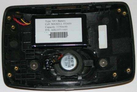
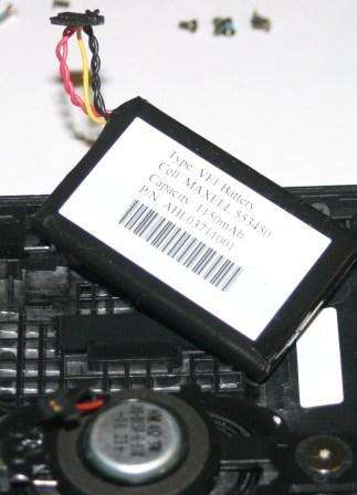
1) The battery was glued to the case, not the mainbord. I originally used my fingers to pull it off - it came away easily - as it still does.
2) I checked the LCD cable connection for seating on the mainboard. Seemed to be properly mounted & the clip connector is operating as I would expect. I them powered it up and tried to wobble the mainboard connector while on the default map screen to see if there is any different behaviour. Nothing different was noted. I also tried moving the flex cable - it was tight in the connector.
3) I carefully tried to move all of the chips on the mainboard - nothing appears loose or burnt.
4) Whle again on the default map screen I proded all of the chips on the mainboard. No difference in behaviour was observed.
 
1) The battery was glued to the case, not the mainbord.
Interesting. I wasn't aware that they had shifted the battery mounting somewhere between the 930 and 940. Previously, there had been an empty space on that side of the board, and the battery was glued there. The different situation that you report certainly eliminates the possibility of board damage due to removal of the battery!

You've done all of the other things that one would expect to do under the circumstances and without special equipment.
 
Any suggestions where I could locate a replacement 940 mainboard? They were never sold in Australia so TT is not going to be particularly helpful.
 
Possibly from one of the repair shops in the UK,
but I would think the only real chance is to find a 940 with a smashed screen on eBay.
 
The 940 was supplied in two versions a Live and non Live variant, the mainly European supplied units were Live, but for countries where Live services are not offered they sold the non Live version, the main board is different in each case - Mike
 
Thanks Mike. That is a useful heads up regarding the two versions of the 940 motherboard. I assume it is 940 - 3 power connector and 940 Live 5 power conectors to the battery.
 
Some developments with my issue. I was lucky enough to have the TT940 connect to my PC without asking me the question to connect YES NO (I have no idea why it allowed me to - and I cannot repeat the occurance).

As such I was able to download a new application to the TT940 and to reset the bios. However the problem remains.

To me, this is narrowing down the issue to a hardware issue. Thinking about it, I am considering that it must be in the ribbon cable connector, as any other failures should lead to complete removal of function.

Would anyone know the ribon cable to the LCD screen connector specificatuons/pin-outs? Maybe the issue is around the touch screen X Y feeds.....
 
Take a close look at the ribbon cable where it bends back on itself, can you see any cracked or damaged tracks in this area?

This is what I have on the internals of a 940 Live:

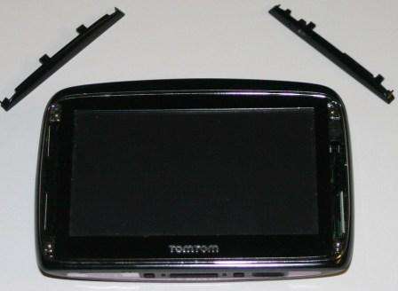
Both side pieces simply unclip from the device, you will need strong thumb nails to get these out though, once removed there are four Torx head screws which are securing the device together.


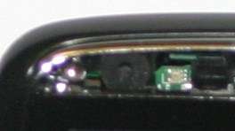
Before we take the screws out a closer look at the right hand side strip now its been removed, this contains two ?windows? the upper on being a simple hole from the microphones, the lower one is the ambient lighting sensor. Interestingly this is a short length plastic ?light pipe? which is employed to carry the light to the sensor which is buried within the device. These light pipes are more often used to feed light to a front panel indicator, and this goes someway in explaining the poor performance of the light sensor when you put the device in demanding conditions (low sunlight dawn/ dusk)


The black ?doughnut? is the microphone, the small white blob to the right of the microphone is the light level sensor, it is a tiny component only a few millimetres across.


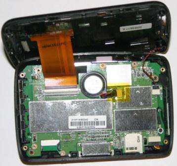
What?s inside the device? With the four corner screws removed the rear case is easy to remove:


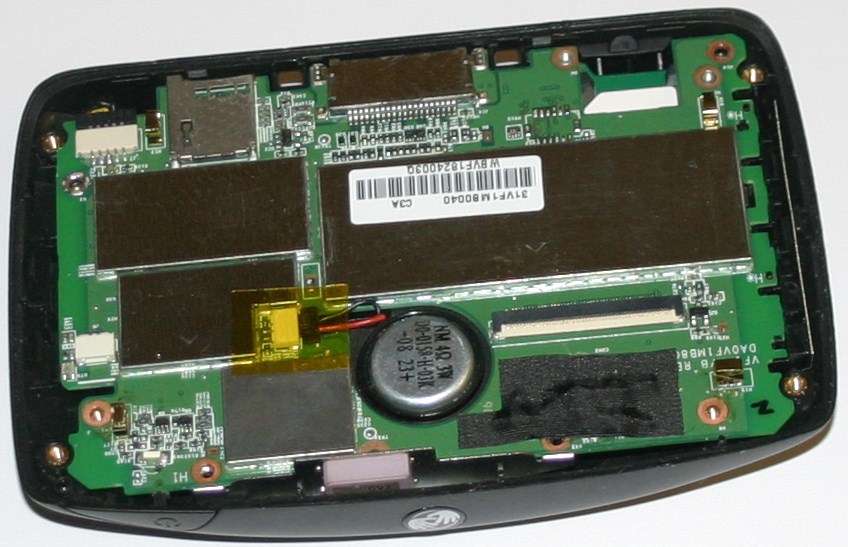
Joining the two halves of the device is the red and black twisted cable on the right, this is the microphone cable and a much larger multi-way ribbon cable. Running left to right along the bottom of the picture is the Sim card slot, the main docking connector, the memory card holder and finally the battery connector. With all the main chips now encased in RF cans there is no ?tin foil? like used to be found in some of the earlier devices.


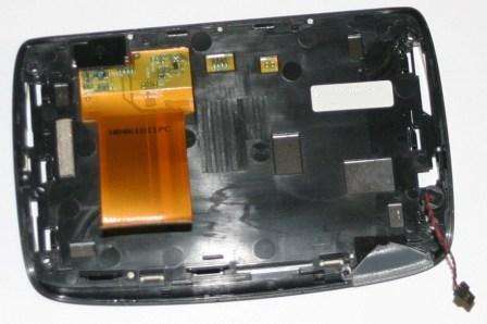
With the battery connector disconnected first the ribbon cable and microphone can be released, this allows both halves of the unit to be separated, above is the screen portion. Surrounding the on/ off switch is another ?light pipe? (lower right corner of the above picture), this is what illuminates red while the device is on charge and green when powered externally and fully charged. It is possible to split the above assembly down even further, the screen is released from the front as it is simply clipped in place.


To extract the main board you have to remove six torx screws, one is partially hidden under the black stick tape to the left of the speaker. Note the screw lower right corner is also used to connect the small aerial board to the main PCB. Make sure you disconnect the battery (lower right) and the speaker plug which is just to the right of the speaker. The PCB is secured to the case with two slots at the bottom of the board either side of the docking connector, lift the board slightly at the top before it can be simply lifted out of the housing.

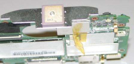
A view with the board removed showing the GPS patch aerial


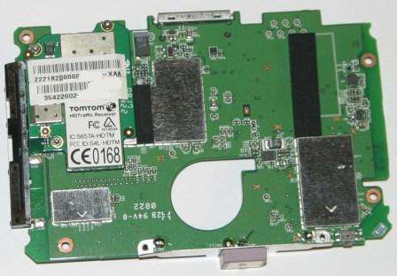
The other side of the PCB, where you can see the HD Traffic receiver, the lower number on the bar coded sticker (top left) is the units IMEI so don?t go showing that in pictures. Again with all the chipsets under metal screen cans there is very little to see.


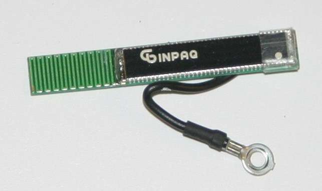
I mentioned the single wire connected to the main PCB via a mounting screw, attached to the other end of the cable is this small FM aerial board, see Here for product details. It would also appear the GPS Patch aerial is from the same company when you look at the product range.


And finally the battery, it is glued into position but can be easily removed, at least they have stopped the rather silly idea of gluing the battery to the main PCB!


- Mike
 
Hi Mike.
Some useful suggestions there. Anything helps.

The ribbon cable is all good - it works on another TT940. Putting the second TT940's screen on the broken one - the same issue occurs. Hence I am sure it is somethng on the mainboard.

I was not sure if it was software or hardware, but the change of application and firmware discussed in my update suggests it is hardware. Hence I have taken a really close liik at the connector (attached to this post). Nothing obvious at all........

Any other suggestions?
 

Attachments

  • DSC_1891 - Copy.JPG
    DSC_1891 - Copy.JPG
    94.8 KB · Views: 348
The last four pins on the right of the connector look a little high compared to the rest, especially the last pair, not too sure what to suggest about trying to fix that though - Mike
 

Ask a Question

Want to reply to this thread or ask your own question?

You'll need to choose a username for the site, which only take a couple of moments. After that, you can post your question and our members will help you out.

Ask a Question

Members online

No members online now.

Latest resources

Forum statistics

Threads
28,911
Messages
195,093
Members
67,861
Latest member
garoutte07

Latest Threads

Back
Top