
Hi all, I have a 720 which smoked when plugged into the car charger. The white feedback wire on the charger must have been damaged which sent hi voltage (13v dc into the unit frying the 5.6v zener diode. Nothing else seems to be damaged. My problem is that the diode is so badly cooked that I can not determine its orientation on the board. I haven't removed the component yet but there appears to be no layout diagram on the bbd. below it.Can anyone tell me whether the cathode or anode faces the bottom of the unit. (ie line on diode to top or bottom) Cant seem to find cct layouts anywhere, ( typical tom tom). Any advice would be appreciated, Cheers Harpo.
You are using an out of date browser. It may not display this or other websites correctly.
You should upgrade or use an alternative browser.
You should upgrade or use an alternative browser.
D8 fried on 720!
- Thread starter Harpo
- Start date
dhn
Moderator
dhn
Moderator
If Mikealder does not reply to this thread within 24 hours, pm him.
So, check back........
So, check back........
Is this any use?
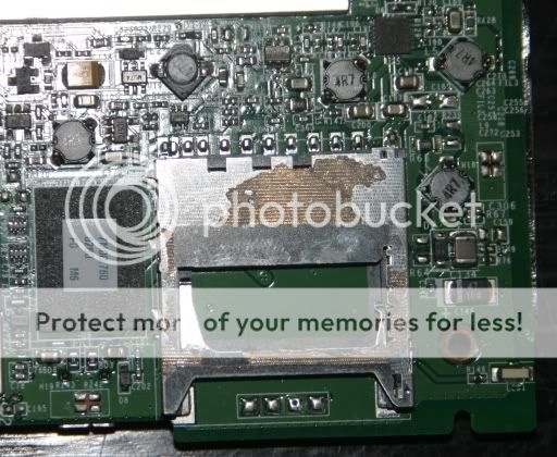
Sorry for the image size but I guess you will need the magnification, this is the area you asked for on the PCB although I can't see any ID marks on the PCB as to which way around D8 needs to be but you know where the damage is on your board - Mike
Sorry for the image size but I guess you will need the magnification, this is the area you asked for on the PCB although I can't see any ID marks on the PCB as to which way around D8 needs to be but you know where the damage is on your board - Mike
Last edited by a moderator:
Thanks Mikealder .From your photo it appears as if the anode or lined side of the diode is facing up. Worst case scenario is that Im wrong and the diode will go pop again, hopfully not taking anything else with it! Thanks again for your help, will keep you posted of results. Cheers Harpo.
canderson
Moderator
- Joined
- Dec 28, 2007
- Messages
- 13,023
- Location
- Colorado, USA
- TomTom Model(s)
- GO720, GO740, GO 1535, Via 1535, Via 1605, GO 52, GO 600, GO 620, GO 630, GO Discover, TomTom Bridge
The "line" is up (away from the board edge) - just checked my 720. However, that would be the cathode end of a diode, wouldn't it? Even for an SMT part? How the devil did you figure this for a 5.6V zener if it was so toastified?Thanks Mikealder .From your photo it appears as if the anode or lined side of the diode is facing up. Worst case scenario is that Im wrong and the diode will go pop again, hopfully not taking anything else with it! Thanks again for your help, will keep you posted of results. Cheers Harpo.
dhn
Moderator
Even for an SMT part? How the devil did you figure this for a 5.6V zener if it was so toastified?
What language is that you just spoke, canderson?

canderson
Moderator
- Joined
- Dec 28, 2007
- Messages
- 13,023
- Location
- Colorado, USA
- TomTom Model(s)
- GO720, GO740, GO 1535, Via 1535, Via 1605, GO 52, GO 600, GO 620, GO 630, GO Discover, TomTom Bridge
That was electronspeak, but I apologize that part of it was in my own unique dialect.What language is that you just spoke, canderson?
"Toastified": The condition of an electronic component once the smoke has been let out of it.
A Note on the Importance of Smoke: Smoke is one of the primary (and critical) materials used in the production of nearly all electronic components. This is easily demonstrated even to those who are unfamiliar with the art of component manufacturing. If you let the smoke out of an electronic part, it immediately ceases to function; quod erat demonstrandum.
You are quite correct Mr Canderson. That would be the Cathode end of a diode. Unfortunately I suffer from a rare form of visual dyslexia usually triggered by the consumption of too much whiskey whilst looking for answers to modern technological problems on my P.C . As for discovering the value and type of the above mentioned component , I happened across an alternative Forum where the exact same problem had occurred (ie. a damaged charger cable had blown the crap out of the diode ) and also in their case the on-board regulator as well . They fixed the problem by replacing the diode d8 with a 5.6 v zener. They also replaced the regulator, which at the time I also identified but which showed no external sighs of damage on my unit. Unfortunately due to my above mentioned ailment I cant seem to re find that particular piece of info. Anyway thanks for confirming my query . I have replaced the burnt out component, but unfortunately " NO CIGAR " . Not sure what to do now other than contact TomTom and complain about how you should not be able to blow up an expensive piece of equipment with charger that they supply with the product, and demand compensation at very least in the form of a warranty repair. Any other suggestions would be appreciated.
canderson
Moderator
- Joined
- Dec 28, 2007
- Messages
- 13,023
- Location
- Colorado, USA
- TomTom Model(s)
- GO720, GO740, GO 1535, Via 1535, Via 1605, GO 52, GO 600, GO 620, GO 630, GO Discover, TomTom Bridge
I'm still at a loss as to why they require a "feedback wire" (otherwise known as "remote sense" in the power supply business). They should have no problem determining the voltage drop across their own (known) piece of cable at a given specific current draw required to maintain constant voltage to the GPS.
Same from me, this voltage feedback cable is an avoidable weak point that really shouldn't be present considering the device can handle a far wider input than just 5,0V
I deal with high power gennerators on a day to day basis (400Hz rather than 50/60Hz stuff) and I avoid cable head sensing wherever possible as its allways the feedback core that breaks sending the voltage through the roof - Its basic electrical design that is poor and shouldn't be needed these days - Mike
I deal with high power gennerators on a day to day basis (400Hz rather than 50/60Hz stuff) and I avoid cable head sensing wherever possible as its allways the feedback core that breaks sending the voltage through the roof - Its basic electrical design that is poor and shouldn't be needed these days - Mike
canderson
Moderator
- Joined
- Dec 28, 2007
- Messages
- 13,023
- Location
- Colorado, USA
- TomTom Model(s)
- GO720, GO740, GO 1535, Via 1535, Via 1605, GO 52, GO 600, GO 620, GO 630, GO Discover, TomTom Bridge
I've always figured that if your I2R losses are that bad at the high end of the current requirement of the device, it's time to get bigger conductors, not dink with the supply voltage to make up for them. Hard to imagine, but I can't think of another reason TomTom would have incorporated a feature like that in their design.Its basic electrical design that is poor and shouldn't be needed these days - Mike
- Joined
- Jun 25, 2008
- Messages
- 79
I haven't seen the diagrams of the 720 but here's what I'm thinking:
The voltage sense is for the battery charger. It sense the voltage at the battery itself, not at the DC input. The goal is to charge the battery as fast and accurately as possible. In order to do so, they force a higher current in the battery when it's power level is low. When the battery recharge, it's voltage will start going up. The sense wire picks-up that voltage increase and will signal the power supply to turn-down the juice.
A Zener diode work like a regulator and is designed to work in over-voltage conditions. A Zener is also designed to be installed the opposite way of a normal diode, in serie with a resistor. (Diodes) If you installed it the "normal way" with the cathode (the white bar) towards the (-), it's no go. It must be connected with the cathode (the white bar) towards the (+) voltage.
A 5.8V Zener will simply keep the voltage at it's pins to 5.8V, no matter the input (to a certain limit, of course). The Zener is an absolute limiter and should be ideally installed in the power adapter, where size doesn't limit the maximum dissipating power as much as when it's surface-mount. Installing it in the device is poor design, IMHO.
If the Zener blew-up, chances are the power adaptor got faulty. I don't think it should ever output the 13.8V ever, even in open loop mode with the sensor wire disconnected. I would expect maybe 6V, not more.
I have read somewhere that some people simply open the power adapter, cut the white wire and solder the pad where the white wire should connect with the pad where the red wire connect, at PCB level. DO NOT FORGET TO CUT THE WHITE WIRE!! I have not done this personally but, what it does is limit the output to what's considered by the adapter as a fully charged battery so, the charging will be slower and possibly not 100%. Since the TT720 already have a very poor live time on batteries, that won't change much in real life and won't damage anything but it will prevent problems with the white wire breaking at the plug level: no more overload!
Connected my 720 to 12v and Toasted the D8 component
I'm trying to fix my GPS after I connected it to 12v by mistake.
I checked inside and found a component that was burnt (D8) after a bit of reading I found that this is a Zener 5.6v diode...
The rest seems to be ok... (at least nothing else looks burnt)
Can someone help me giving me some directions on how to replace this diode?
Never touched a circuit board before, but I'm willing to give it a try before throwing my unit to the bin...
These are the photos of the circuit....


THANKS!
I'm trying to fix my GPS after I connected it to 12v by mistake.
I checked inside and found a component that was burnt (D8) after a bit of reading I found that this is a Zener 5.6v diode...
The rest seems to be ok... (at least nothing else looks burnt)
Can someone help me giving me some directions on how to replace this diode?
Never touched a circuit board before, but I'm willing to give it a try before throwing my unit to the bin...
These are the photos of the circuit....
THANKS!
dhn
Moderator
Welcome to TTF.
Supermod Mikealder should see this thread and give advise. check back.
Supermod Mikealder should see this thread and give advise. check back.
@Nano07, are you used to soldering repairs to SMT boards? and do you have the necessary equipment, if no is the answer to either of these3 questions I wouldn't bother trying to be honest.
Don't think I am just fobbing you off with the above answer but, if you aren't used to working on an SMT board with the correct type of soldering iron you won't fix the device but will burn your fingers - Mike
Don't think I am just fobbing you off with the above answer but, if you aren't used to working on an SMT board with the correct type of soldering iron you won't fix the device but will burn your fingers - Mike
@mike Hi Mike, Thanks for answering to my post.
No, I have never done soldering to SMT boards.
I was ready to throw it on the bin until I read that it might be only this $.50c component that might be burnt, so I thought I'd give it a try...
I live in a small town and couldn't find someone to do it for me, so I'm willing to give it a try.
Could you point me in the right direction on what type of tools do I need? I didn't know the term SMT so I think a search in youtube on HOWTO do SMT soldering might give me some tips, but I would appreciate any advice you give me as well.
Also I did a search on Zener 5.6v Diode and found these... would they be ok?
NEW 25 X 5.6V IN4734 4734 1W Zener Diodes Freeship | eBay
Thanks man! I appreciate your help...
Ask a Question
Want to reply to this thread or ask your own question?
You'll need to choose a username for the site, which only take a couple of moments. After that, you can post your question and our members will help you out.
Similar Threads
Forum statistics
Latest Threads
-
Go 920 start up
- Started by BigL
-
FREEING UP SPACE ON HARD DRIVE
- Started by ATLAS1
-
HOW TO ADD CAMERA ALERT / .OV2 FILES TO VIA1535TM
- Started by ATLAS1
-
MyDrive Connect not loading
- Started by George L
-
VIA1535TM SLOW SATELLITE DETECTION
- Started by ATLAS1
-
Transferring routes to new Tom Tom
- Started by Flowerlady
-
Problem with sunlight
- Started by Flowerlady
-
In a mess with my TomTom Go 5000
- Started by Patrick56
-
Route planner not working
- Started by jsfirth48